


.png)


![[HOONIGAN] Ken Block's GYMKHANA NINE](https://img.youtube.com/vi/_bkX5VkZg8U/maxresdefault.jpg)


![[HOONIGAN] KEN BLOCK'S GYMKHANA SEVEN: WILD IN THE STREETS OF LOS ANGELES](https://cdn.motor1.com/images/mgl/2KlO4/s1/ken-block-london-tour-directors-cut.jpg)


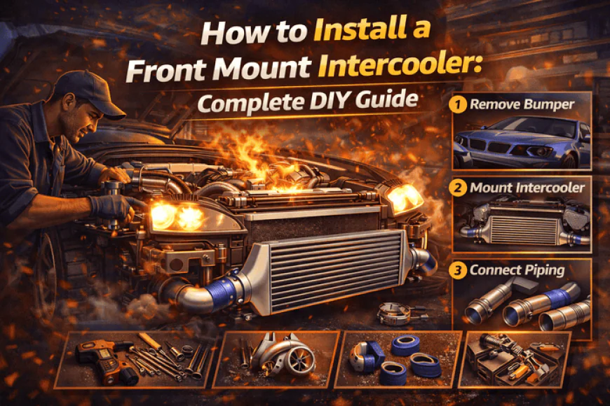
How to Install a Front Mount Intercooler: Complete DIY Guide
Complete FMIC installation guide with tools, pipework, mounting, and tuning considerations for turbocharged cars.
Why Every Serious Turbo Build Needs a Front Mount Intercooler
If you're building a turbocharged car for serious power, a front mount intercooler (FMIC) isn't optional — it's essential. The stock side-mount or top-mount intercooler that came with your car was designed for factory power levels, factory boost pressures, and conservative heat management. Once you start pushing 300+ bhp, upgrading the turbo, or increasing boost beyond stock specifications, that factory intercooler becomes a catastrophic bottleneck.
Heat soak destroys power. As your intercooler heats up from repeated pulls or track use, the density of the air entering your engine drops dramatically. Less dense air means less oxygen. Less oxygen means less power and — critically — increased risk of detonation. A properly sized front mount intercooler solves this by positioning a much larger core directly in the airflow at the front of the car, maximizing cooling efficiency.
Installing a FMIC is one of the most rewarding modifications you can do yourself. It's mechanically straightforward — no engine internals to touch, no complex wiring, just removing old piping and fitting new components. With basic tools, a weekend, and this complete guide, you can install a front mount intercooler that transforms your turbo car's performance and reliability.
As we covered in our guide on 500bhp Supra Build Cost, the intercooler is a non-negotiable supporting modification for any serious power build. Let's walk through exactly how to install one properly.
What You'll Learn:
- Required tools and parts list
- Complete step-by-step installation process
- Pipework routing and fabrication
- Boost leak testing procedures
- Post-installation tuning considerations
- Common mistakes and how to avoid them
Tools and Parts Required
Essential Tools
|
Tool |
Purpose |
Estimated Cost |
|
Socket set (10-19mm) |
Removing brackets, clamps, bumper |
£30-80 if buying new |
|
Combination spanners |
Hard-to-reach bolts |
£20-50 |
|
Ratchet extensions |
Deep access |
£15-30 |
|
Torque wrench |
Proper bolt tension |
£30-100 |
|
Flat-blade screwdrivers |
Hose clamps, clips |
£10-20 |
|
Angle grinder or hacksaw |
Bumper trimming (if needed) |
£25-60 |
|
Drill + bits |
Mounting brackets |
£30-80 |
|
Jack and axle stands |
Safe working height |
£60-150 |
|
Cable ties/zip ties |
Securing wiring, hoses |
£5-10 |
|
Grease/assembly paste |
Preventing seized bolts |
£5-10 |
Parts Checklist
Included in most FMIC kits:
- Intercooler core
- Hot-side piping (turbo to intercooler)
- Cold-side piping (intercooler to throttle body)
- Silicone couplers/hoses
- T-bolt clamps or worm-drive clamps
- Mounting brackets
- Hardware (bolts, nuts, washers)
Usually NOT included (buy separately):
- Blow-off valve/bypass valve (if not reusing stock)
- Additional clamps (kits often include minimum needed)
- Vacuum hoses for BOV
- Breather filters (if relocating crankcase breather)
- Boost leak tester (or make one — see below)
- Coolant for top-up (if draining cooling system)
Consumables:
- Engine oil (if draining for turbo access)
- Coolant
- Degreaser/brake cleaner
- Thread locker (blue Loctite)
- Zip ties
Pre-Installation Preparation
1. Choose Your Work Location
Ideally:
- Level concrete surface
- Good lighting
- Protection from weather
- Space to lay out parts
- Access to power for tools
A garage is ideal. A driveway works. Avoid grass (jack stands sink) or slopes (dangerous).
2. Read the Kit Instructions
CRITICAL: Even with this guide, read your specific kit's instructions. Every car and kit has unique quirks. Know what you're getting into before you start.
3. Test-Fit Before Removing Anything
Lay out the intercooler and piping next to the car. Verify:
- Intercooler fits in the space available
- Piping reaches from turbo to intercooler to throttle body
- No obvious interference with radiator, AC, or chassis rails
- Mounting brackets align with chassis mounting points
Finding fitment issues AFTER removing the stock system is frustrating and delays reassembly.
4. Photograph Everything
Take photos of:
- Stock intercooler piping routing
- Hose connections
- Bracket positions
- Wiring that needs to be moved
- Sensor locations
You'll reference these during reassembly if you get confused.
5. Disconnect Battery
Safety first. Disconnect the negative terminal to prevent electrical shorts or accidental starter engagement while working.
Step-by-Step Installation Process
Step 1: Remove Front Bumper
Most FMIC installs require bumper removal for access.
Typical process (varies by car):
- Remove undertray/splash guards (usually 8-12 bolts/clips)
- Locate bumper mounting bolts (usually 2-4 per side in wheel well)
- Remove grille mounting clips/bolts
- Disconnect fog light wiring (if fitted)
- Carefully pull bumper forward off mounting tabs
- Set aside safely (protect paint)
Time: 30-60 minutes
Pro tip: Have a helper for this step. Bumpers are awkward to maneuver alone.
Step 2: Remove Stock Intercooler System
For side-mount intercoolers (common on Subarus, some Nissans):
- Loosen all hose clamps on hot-side piping (turbo to intercooler)
- Loosen clamps on cold-side piping (intercooler to throttle body)
- Disconnect any vacuum lines or sensors
- Remove mounting bolts securing intercooler
- Carefully remove piping (may need to wiggle and rotate)
- Remove intercooler
For top-mount intercoolers (common on WRX/STI):
- Remove engine cover
- Disconnect charge pipe from throttle body
- Loosen clamps securing intercooler to turbo outlet
- Remove intercooler mounting bolts
- Lift intercooler out (may need to move wiring/hoses aside)
Time: 45-90 minutes depending on accessibility
Common issues:
- Seized bolts (penetrating oil the night before helps)
- Brittle old hoses (may tear — replace them)
- Sensors corroded onto piping (careful removal required)
Step 3: Prepare Mounting Location
With the stock system out:
- Clean all mounting surfaces (brake cleaner or degreaser)
- Test-fit new intercooler in position
- Mark mounting holes with marker or punch
- If drilling new holes, use step drill bit and go slowly
- Apply anti-seize to new mounting bolts
- Loosely install mounting brackets (don't fully tighten yet)
Time: 30-45 minutes
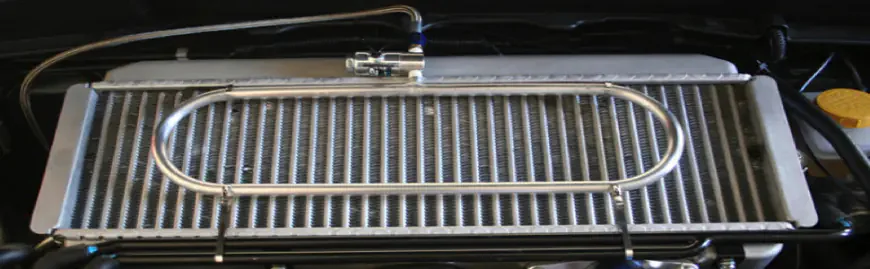
Step 4: Install Intercooler Core
- Position intercooler on mounting brackets
- Align mounting holes
- Install bolts finger-tight initially
- Check clearances (minimum 10-15mm from radiator, AC condenser, fans)
- Verify intercooler sits level
- Torque mounting bolts to spec (typically 15-20 Nm)
Critical: The intercooler must be secure but not over-torqued. Aluminum is soft and strips easily.
Step 5: Route Hot-Side Piping (Turbo to Intercooler)
This is the most complex step. Hot-side piping carries compressed air from the turbo outlet to the intercooler inlet.
Typical routing:
- Start at turbo outlet — fit first coupler and clamp
- Route pipe avoiding heat sources (exhaust, engine block)
- Work toward intercooler, joining sections with couplers
- Maintain smooth bends (avoid kinks or sharp angles)
- Secure with clamps at every joint
- Leave clamps loose until final fitment check
Common challenges:
- Interference with engine bay components (AC lines, brake master cylinder, wiring)
- Insufficient clearance to firewall
- Pipe length too short or too long
Solutions:
- Trim/modify brackets if interference occurs
- Use longer couplers to gain adjustment range
- Heat and bend aluminum piping if needed (carefully)
Time: 60-120 minutes (longest step)
Step 6: Route Cold-Side Piping (Intercooler to Throttle Body)
Cold-side is usually easier — shorter run, fewer obstacles.
- Fit coupler to intercooler outlet
- Route pipe toward throttle body
- Ensure pipe doesn't contact moving parts (belts, pulleys)
- Connect to throttle body with coupler and clamps
- Verify blow-off valve location and connection
Time: 30-60 minutes
Step 7: Install Blow-Off Valve (BOV)
Most FMIC kits include a BOV flange in the cold-side piping.
- Position BOV with vacuum port facing toward accessible vacuum source
- Install gasket (don't reuse old gasket)
- Bolt BOV to flange (torque evenly in star pattern)
- Connect vacuum hose from intake manifold to BOV
- Ensure hose routing doesn't kink or contact hot surfaces
Adjustment: Most BOVs have adjustable spring preload. Start with factory setting. Adjust later if needed.
Step 8: Reconnect Sensors and Hoses
- Reinstall MAP sensor (if moved)
- Reconnect charge temperature sensor (IAT)
- Route crankcase breather (if affected by piping)
- Secure all wiring with zip ties (away from heat and moving parts)
- Reconnect vacuum lines
Pro tip: Label wires and hoses before removal. Saves confusion during reassembly.
Step 9: Final Fitment Check
Before tightening everything permanently:
- Check all clearances again
- Verify no interference with engine movement (rock engine gently)
- Confirm no contact with radiator fans
- Ensure BOV opens freely
- Check wastegate actuator movement (should move freely)
Now tighten all clamps.
Clamp tightness is critical:
- Too loose: Boost leaks
- Too tight: Damages couplers or pipes
- Just right: Firm but not crushing the coupler
T-bolt clamps: Torque to 8-10 Nm Worm-drive clamps: Tighten until snug, then 1/4 turn more
Post-Installation: Critical Steps
Boost Leak Testing
This is non-negotiable. A boost leak at high power levels is dangerous.
DIY boost leak tester:
- Block throttle body inlet (plate or rubber cap)
- Attach air compressor fitting to intercooler piping
- Pressurize to ~15 psi
- Spray soapy water on all joints and couplers
- Look for bubbles indicating leaks
Professional method: Drive to dyno or tuner, they'll test properly with smoke or pressure testing equipment.
Fix any leaks before driving under boost.
ECU Considerations
CRITICAL: If your FMIC has significantly more volume than the stock intercooler (most do), the ECU may need adjustment.
Larger intercooler volume means:
- Slower throttle response (more air to pressurize)
- Potentially different MAF sensor readings
- Possible BOV adjustments needed
For naturally aspirated ECU tuning basics, see our ECU Remap vs Piggyback Tuner. For turbo-specific tuning, consult a professional.
At minimum:
- Check for fault codes after installation
- Monitor AFR (air/fuel ratio) carefully on first drives
- Watch for MAF scaling issues
Ideally: Get a dyno tune or custom map from a specialist. This is especially important if running SR20DET 400bhp Build.
First Drive Protocol
- Idle check: Let car idle for 5-10 minutes, listen for leaks or unusual sounds
- Low-boost test: Drive gently, no more than 5 psi boost for first 10 miles
- Visual inspection: Stop, check for leaks, loose clamps, or heat issues
- Medium boost: Gradually increase to 10-12 psi, monitor temps
- Full boost: Only after confirming system is leak-free and temps are stable
Monitor:
- Intake air temperature (should drop significantly vs stock)
- Boost pressure (should be consistent, no spikes or drops)
- AFR (should remain safe, not lean)
Bumper Modification
Many FMICs require bumper trimming for proper airflow.
Where to cut:
- Behind front grille opening
- Lower bumper section in front of intercooler
How to cut:
- Mark cutting line carefully
- Use angle grinder or Dremel with cutting disc
- Cut conservatively (can remove more, can't add back)
- Smooth edges to prevent cracking
- Consider mesh for aesthetic finish
Common Mistakes and How to Avoid Them
1. Over-Tightening Clamps
Symptoms: Crushed couplers, cracked piping, leaks
Fix: Use torque wrench for T-bolt clamps. For worm-drive, tighten until snug plus 1/4 turn only.
2. Poor Pipework Routing
Symptoms: Kinked pipes, restricted airflow, contact with hot/moving parts
Fix: Plan routing before cutting pipes. Maintain smooth bends. Use extra couplers for adjustment.
3. Ignoring Boost Leaks
Symptoms: Loss of power, inconsistent boost, potential engine damage from running lean
Fix: Pressure test before driving. Fix every leak.
4. Not Securing Wiring
Symptoms: Wiring melted on exhaust, sensors failing, electrical faults
Fix: Use heat-resistant zip ties. Route away from hot surfaces. Check clearances with engine running.
5. Neglecting Tuning
Symptoms: Poor throttle response, check engine light, potential detonation
Fix: Get proper tune. Larger intercooler = different airflow characteristics = ECU needs adjustment.
Performance Gains and What to Expect
Power Gains
Directly from FMIC alone: 5-15 bhp
The FMIC doesn't add power directly — it enables consistent power by maintaining lower intake temperatures.
Where you'll notice difference:
- Consecutive pulls show consistent power (no heat soak)
- Higher ambient temperatures don't kill power
- Safer to run more boost (cooler air = less detonation risk)
- Power holds on track days (multiple sessions without performance drop)
Temperature Improvements
Stock intercooler typical: +40-60°C above ambient after hard driving
Quality FMIC: +10-20°C above ambient
This temperature drop is the real benefit — cooler air is denser, safer, and more consistent.

Frequently Asked Questions
Can I install a FMIC without removing the bumper?
On some cars, yes, but it's significantly harder and risks damaging the bumper or intercooler. Removing the bumper adds 30 minutes but makes installation far easier.
Do I need a tune after FMIC installation?
Not always, but it's recommended. Cars with MAF sensors may need adjustment. Cars already tuned near their limits will benefit from optimisation.
Q3: Will an FMIC cause turbo lag?
Slightly, yes. The larger volume means more air to pressurise. Typically adds 200-400 rpm to spool time. The benefits outweigh this minor drawback.
Can I reuse stock couplers and clamps?
Couplers: Maybe, if not brittle or damaged. Clamps: If T-bolt style and undamaged, yes. Worm-drive clamps: Replace (they stretch and lose clamping force).
How often should I clean my intercooler?
Externally: Every 6-12 months (remove bugs, dirt). Internally: Only if oil contamination (from turbo failure or catch can issues). Most intercoolers never need internal cleaning.
What size intercooler do I need?
General rule: Core size should match power level. For 300-400 bhp, 600x300x76mm core. For 400-600 bhp, 600x300x100mm. For 600+ bhp, 700x300x100mm or larger.
Will an FMIC fail an MOT?
No, provided it doesn't block airflow to the radiator and doesn't cause the car to overheat. Some MOT testers note "non-standard cooling system" as advisory. For MOT considerations with modified suspension and other upgrades, see our Passing MOT with Modified Suspension.
Related Articles
 Like
0
Like
0
 Dislike
0
Dislike
0
 Love
0
Love
0
 Funny
0
Funny
0
 Angry
0
Angry
0
 Sad
0
Sad
0
 Wow
0
Wow
0